Computer Architecture + Operating System for Self-Study

This is an article I wrote after reading a book on computer architecture and operating systems that I studied on my own.
Ch.01 Getting Started with Computer Architecture
1.1 Why You Should Know Computer Architecture
Problem solving
It can be solved when the problem is in the computer architecture, not in the code.
Performance, capacity, cost
It is possible to develop while considering performance, capacity, and cost, which are difficult to understand with grammar alone.
1.2 The Big Picture of Computer Architecture
The structural knowledge of a computer consists of ‘information that a computer understands’ and ‘the four core components of a computer.’
Information that computers understand
Data refers to static information such as numbers, letters, images, and videos.
Instructions are the information that actually moves the computer, and data is a kind of material for instructions.
The four core components of a computer
중앙처리장치(CPU, Central Processing Unit), 주기억장치(메모리, main memory), 보조기억장치(secondary storage), 입출력장치(input/output(I/O) device)이다.
Memory stores the instructions and data of the currently running program.
The CPU is a component that reads instructions stored in memory, interprets them, and executes them. It consists of an arithmetic logic unit (ALU), registers, and a control unit (CU, Control Unit).
The ALU performs calculations, the registers act as small storage devices inside the CPU, and the control unit sends out control signals (reading and writing memory, etc.) and interprets commands.
Auxiliary storage refers to memory that does not lose stored contents even when the power is turned off.
Input/output devices are components that are connected to the outside of the computer and can exchange information with the inside of the computer.
Mainboard and system bus
The above core components are connected to the motherboard. Information is exchanged between components through various buses on the motherboard. The system bus is a bus that connects core components and consists of an address bus, data bus, and control bus.
finish
- A program must be stored in memory in order to run.
Ch.02 Data
2.1 How to represent numbers with 0 and 1
Information unit
Bit: The smallest unit of information that represents 0 and 1 Word: The unit of information size that the CPU can process at once
binary scale
Binary: A method of representing numbers using 0 and 1
Creating negative numbers using 2's complement: Flip all 0s and 1s and add 1. Positive and negative numbers are distinguished through flags.
hexadecimal system
Because binary numbers are too long, hexadecimal is used, assigning A to F for 10 to 15.
2.2 How to represent characters with 0 and 1
Character sets and encodings
Character set: A collection of characters that a computer can understand Encoding: A process of encoding, a process of converting characters into character codes made up of 0 and 1 Decoding: A process of interpreting codes, a process of converting character codes expressed as 0 and 1 into characters
ASCII code
ASCII code: A 7-bit representation of a character code consisting of 0 and 1, with 1 bit used as a parity bit for error detection.
It cannot express other language characters, including Korean, and various special characters. Therefore, language-specific encoding methods emerged.
Unicode and UTF-8
Unicode: A unified character set with multiple encoding methods.
UTF-8 encoding: An encoding method that expresses Unicode in 8 bits, and can use from 1 to 4 bytes.
Verification problem
- Find the negative of 1101(2) using 2's complement representation.
1101
// 1. Flip all bits.
0010
// 2. Add 1.
0011
Ch.03 Command
3.1 Source Code and Commands
High-level and low-level languages
High-level programming language: A language that is easy for humans to understand.
Low-level programming language: A language that a computer understands and executes.
Low-level languages include machine language and assembly language.
Machine code: A language made up of binary numbers consisting of 0s and 1s.
Assembly language: A language composed of symbols that correspond 1:1 to machine language.
Compiled and interpreted languages
Compile language: A language that is converted into a low-level language by a compiler. The source code is converted into object code by the compiler.
Interpreter language: The source code is executed line by line by the interpreter.
3.2 Command Structure
Operation codes and operands
An instruction consists of an operation code and an operand.
Operation code: A code that indicates the function of a command. Indicates the operation to be performed by the command.
Operand: Data to be used in an operation or the memory address where the data to be used in an operation is stored.
The operand field is also called the address field. Operands can be 0 or 1 or more.
The operation codes vary depending on the type of CPU. Representative examples include data transmission, arithmetic/logical operations, control operations, and input/output operations.
Addressing method
Effective address: The address to which the instruction refers to the operand.
Addressing mode: How an instruction references its operands.
- Immediate addressing mode: A method of directly describing the operand in the instruction.
- Direct addressing mode: When the operand is a memory address, this is a method of directly describing the memory address.
- Indirect addressing mode: When the operand is a memory address, this is a method of describing the memory address where the memory address is stored.
- Register addressing mode: When the operand is a register, this is the method of describing the register number.
- Register indirect addressing mode: When the operand is a register, this is a method of describing the memory address where the register number is stored.
Stacks and Queues
stack
Stack: It is a last in first out (LIFO) structure. Inserting data is called push, and taking data out is called pop.
cue
Queue: It is a first-in, first-out (FIFO) structure. Inserting data is called enqueue, and taking data out is called dequeue.
Ch.04 How the CPU Works
4.1 ALU and Control Unit
ALU
The ALU receives operands from registers and control signals from the control unit and performs operations.
Based on the information received, the result value or flag is output to the register.
Flags contain additional status information about the result of an operation.
Control device
Information received by the control unit
- clock signal
- Command: Command received from the command register
- Flags: Flags received from the flag register
- Control signal: Control signal received from the control bus of the system bus
The destination where the control device sends out the control signal
- Registers inside the CPU
- ALU inside the CPU
- Memory or input/output devices (control bus) outside the CPU
4.2 Register
A register is a small temporary storage device inside the CPU that stores instructions within a program or data used in operations.
Registers you must know
Each CPU has different types of registers.
There are eight common registers.
- Program Counter (PC): Stores the address of the next instruction to be executed.
- Instruction Register (IR): Stores the currently executing instruction.
- Memory Address Register (MAR): Stores the address used when accessing memory.
- Memory Buffer Register (MBR): Stores data used when accessing memory.
- Flag Register (FR): Stores status information about the operation results.
- General purpose registers (AX, BX, CX, DX): Store data used in operations.
- Stack Pointer (SP): Stores the top address of the stack.
- Base Pointer (BP): Stores the lowest address of the stack (base address)
Addressing method using specific registers (1): Stack addressing method
Stack addressing is a method of specifying the address of the stack using the stack pointer (SP) register.
Addressing method using a specific register (2): Displacement addressing method
This is a method of calculating the effective address using the operand field value (displacement).
- Displacement addressing specifies an effective address using the operand field value (displacement) and a specific register.
- The relative addressing method specifies the effective address using the operand field value (displacement) and the program counter (PC) register.
- The base register addressing method specifies an effective address using the operand field value (displacement) and the base register (BP) register.
Verification problem
- Find the register that matches the description in the view and fill in the blanks.
Flag register: A register that stores additional information about the results of operations or CPU statusProgram counter: A register that stores the address of an instruction to be fetched from memoryGeneral register: A register that can store both data and addressesInstruction register: A register that stores the instruction to be interpreted
4.3 Instruction Cycle and Interrupts
Command cycle
The process of processing one instruction is called an instruction cycle.
Fetch Cycle: Process of retrieving instructions from memory Execute Cycle: Process of executing instructions Indirect Cycle: Process of processing instructions using indirect addressing
interrupt
An interrupt is a signal that interrupts the CPU's work.
Synchronous Interrupt: An interrupt generated by the CPU. It is also called an exception. There are faults, traps, aborts, software interrupts, etc.
Asynchronous Interrupt: An interrupt generated by an external device. Also called hardware interrupt.
Hardware interrupt: An interrupt that acts like a notification. For example, there are timer interrupts, keyboard interrupts, etc.
Hardware interrupt processing order
- The input/output device sends an interrupt request signal to the CPU.
- The CPU always checks for an interrupt request signal before fetching an instruction at the end of an execution cycle.
- The CPU acknowledges the interrupt request and checks the interrupt flag to see if it can currently accept the interrupt.
- If the interrupt can be accepted, the CPU backs up the work it has done so far.
- The CPU executes the interrupt service routine by referencing the interrupt vector.
- After the interrupt service routine execution is complete, the CPU restores the backed up work.
Interrupt request signal: A signal that notifies the CPU of an interrupt request. Interrupt requests are confirmed through the interrupt flag in the flag register.
Hardware interrupts include interrupts that can be blocked with interrupt flags (maskable interrupts) and interrupts that cannot be blocked (non-maskable interrupts).
Interrupt service routine: A routine that is executed when an interrupt occurs and is stored in memory. It is executed by referencing the interrupt vector.
Interrupt vector: A table that stores the addresses of interrupt service routines. It contains information to distinguish each interrupt.
Interrupt vector table: A table that contains interrupt vectors. The interrupt vector table is stored in memory.
Ch.05 CPU Performance Improvement Techniques
5.1 Design Techniques for Fast CPUs
Clock
Clock speed: Measured in Hertz (Hz). Indicates how many times a clock signal occurs per second.
Core and multicore
Core: A computing unit that exists inside the CPU.
Multi-Core: Multiple cores exist in one CPU.
Threads and multithreading
Thread: A unit of flow executed within a process.
Hardware Thread: A unit of instruction that one core processes simultaneously. A CPU that processes multiple instructions simultaneously with one core is called a multithreaded CPU. Also called a logical processor (Logical Processor).
Software Thread: A unit that runs independently in a program. Dividing a program into multiple threads and executing them simultaneously is called multithreaded programming.
Multi-Core Processor: A CPU with multiple cores in one CPU.
Multi-Thread Processor: A CPU in which a single processor processes multiple threads simultaneously.
Verification problem
- Core
5.2 Command Parallel Processing Techniques
Command pipeline
The process of processing a command is divided into similar time intervals as follows:
- Instruction Fetch: The process of retrieving an instruction from memory
- Instruction Decode: The process of interpreting instructions
- Instruction Execute: The process of executing a command
- Write Back: The process of saving the results of command execution.
A CPU can process instructions simultaneously as long as the steps do not overlap. This is called a command pipeline.
Command Pipeline: A technique for dividing the command processing process and processing it simultaneously.
However, pipeline risks follow.
Data Hazard: When the result of executing a command affects the execution of the next command. It is caused by dependencies between commands. Control Hazard: Caused by sudden changes in the program counter. It is solved with branch prediction. Structural Hazard: When different instructions use the same CPU components (ALU, registers, etc.).
Superscalar
A technique that uses multiple command pipelines. Divide instructions into multiple pipelines and process them simultaneously (similar to a multi-threaded processor).
Out-of-Order Execution (OoOE)
A technique that processes commands that require the execution results of commands first, rather than processing commands sequentially.
5.3 CISR and RISC
instruction set
Instruction Set: A set of instructions that a CPU can process. It is also called Instruction Set Architecture (ISA).
The instruction sets of modern CPUs are broadly divided into CISC and RISC.
CISC
CISC(Complex Instruction Set Computer): Complex instruction set. Utilizes a variety of powerful commands. It can handle complex tasks with a relatively small number of commands.
Command pipelining has some disadvantages.
RISC
RISC(Reduced Instruction Set Computer): Simple instruction set. The number of commands is small, and the function of each command is simple. Command pipelining is easy.
Uses the load-store structure. Minimize memory access and use a lot of registers.
Ch.06 Memory and Cache Memory
6.1 RAM Features and Types
RAM Features
RAM stores the target to be executed. However, since it is a volatile storage device, the stored contents are lost when the power is turned off.
RAM capacity and performance
If the RAM capacity is small, the program to be executed is frequently retrieved from the auxiliary storage device, which increases the execution time.
Types of RAM
- DRAM (Dynamic RAM): RAM in which stored data is dynamically erased, requiring periodic reactivation to prevent data loss.
- SRAM (Static RAM): RAM where the stored data is static, so the input/output speed is generally faster than DRAM. It is used as cache memory.
- SDRAM (Synchronous RAM): DRAM synchronized with a clock signal.
- DDR SDRAM (Double Data Rate SDRAM): This is the most popular type of RAM. SDRAM, which increases bandwidth and speeds up the speed.
- DDR2 SDRAM has twice the bandwidth of SDR SDRAM,
- For DDR4 SDRAM, it has 16 times the bandwidth.
6.2 Memory address space
Physical and logical addresses
Addresses that indicate the location of information stored in memory include physical addresses and logical addresses.
A physical address is the address used by memory hardware, which is the address on the hardware where information is actually stored.
A logical address is an address used by the CPU and the running program, and is an address starting from 0 assigned to each running program.
For a CPU to interact with memory, a process of converting logical addresses into physical addresses is required.
This process is performed by a hardware called the Memory Management Unit (MMU).
The MMU converts the logical address and the base register (the program's base address) value into a physical address.
Memory protection techniques
The limit register prevents the execution of instructions that could invade the domain of other programs.
Base register value <= program's physical address range < Base register value + limit register value
You can see that this is the case.
If the CPU attempts to access a logical address higher than the limit register, it generates an interrupt (trap) and stops execution.
6.3 Cache Memory
It starts with the idea that buffering is necessary because the time it takes for the CPU to access memory is slower than the CPU's computational speed.
Memory Hierarchy
In general, it follows the following proposition:
Storage devices close to the CPU are fast, while storage devices farther away are slow. Fast storage devices have small storage capacities and are expensive.
cache memory
It is an SRAM-based storage device located between the CPU and memory.
Some data to be used by the CPU is brought from memory to cache memory in advance and written.
Typically, in a hierarchical cache memory (L1-L2-L3 cache), L1 and L2 are located within the core, and L3 cache is located outside the core. In case of multi-core, L3 is also shared and used.
locality of reference
First, let's look at the basic content.
Because cache memory has a smaller capacity than memory, it stores some of the information in memory. Mainly, it predicts and stores objects that the CPU is likely to use frequently.
If the predicted data is correct and the data in the cache memory is used by the CPU, it is called a cache hit, and if it is incorrect, it is called a cache miss.
cache hit ratio
Cache Hit Count / (Cache Hit Count + Cache Miss Count)
The principle of locality of reference is how cache memory determines which data to retrieve from memory. The main trends are as follows:
The CPU tends to re-access memory spaces it has recently accessed. Let's look at the code that prints the second multiplication table as follows.
public static void main(String[] args) {
  int num = 2;
  for (int i = 1; i <= 9; i++) {
    System.out.printf("%d X %d = %d\n", num, i, num * i);
  }
}
/** 실행 결과

* 2 X 1 = 2
* 2 X 2 = 4
* ...
* 2 X 8 = 16
* 2 X 9 = 18
**/
The CPU tends to access memory spaces close to where it has accessed them (spatial locality). Programs that the CPU is trying to execute are usually grouped together with related data.
Each function within the program is also grouped together.
Verification problem (p. 185)
Read the following description and write whether it is about SRAM or DRAM. View: SRAM, DRAM The question content has been modified according to the issue posted on the book GitHub.
- SRAM
- DRAM
- DRAM
- SRAM
Ch.07 Auxiliary memory devices
7.1 Various auxiliary memory devices
hard disk
Data is stored based on the principle of magnetic fields.
It consists of multiple layers of platters and spindles.
The platter is covered with a magnetic material that stores the N and S poles that act as 0 and 1.
The spindle rotates the platter.
The component that reads and writes data on the platter is the head, which is attached to the disk arm.
Platters store data in units of tracks and sectors. A logical unit that connects the locations of the same tracks on multiple layers of platters is called a cylinder.
Data access process on hard disk
The time it takes for a hard disk to access stored data is divided into seek time, rotational delay, and transfer time.
Seek time refers to the time it takes to move the head to the track where the data to be accessed is stored.
Rotational latency refers to the time it takes for the platter to rotate to where the head is.
Transfer time refers to the time it takes to transfer data between a hard disk and a computer.
flash memory
It is a semiconductor-based storage device that can read and write data electrically.
There are two types of flash memory: NAND flash memory and NOR flash memory, but NAND flash memory is mainly used.
Flash memory has units called cells.
Depending on the number of bits that can be stored in one cell, there are 1-bit (SLC), 2-bit (MLC), 3-bit (TLC), and 4-bit (QLC).
QLC is not widely used, and the differences between the other three are as follows:

This can be summarized in one table.
Let's learn about units larger than cells.
Cells, which are the storage units of flash memory, come together to form pages, pages come together to form blocks, blocks come together to form planes, and planes come together to form dies.
Reading and writing in flash memory is done on a page-by-page basis. However, deletion is done in larger units, called blocks.
At this point, a page can have three states: It is in Free, Valid, and Invalid states.
The Free state is a state in which no data is stored and new data can be stored.
The Valid state is a state in which valid data is already stored.
Invalid state is a state where invalid data, called garbage values, is stored.
Since flash memory cannot be overwritten, if there is a value that you want to modify, change it to Invalid and save the modified value in the remaining pages. Flash memory provides a garbage collection function to clean up these invalid values.
7.2 Definition and Types of RAID
If the capacity is the same, configuring RAID with small hard disks is superior in terms of performance and stability than using large hard disks.
Definition of RAID
RAID (Redundant Array of Independent Disks) is a technology that mainly uses hard disks and SSDs to use multiple physical auxiliary storage devices as if they were one logical auxiliary storage device for data security or high performance.
Types of RAID
The RAID configuration method is expressed as RAID level, and representative levels include RAID 0 to RAID6.
Let's learn about 0, 1, 4, 5, and 6
RAID 0 is a method of simply dividing and storing data.
Data that is stored in a distributed manner is called a stripe, and storing it in this way is called striping.
It may improve input/output speed, but stored information may not be secure.
RAID 1 is also called mirroring because it creates copies. Because it creates an original and a copy, the write speed is slower than RAID 0.
Backup and recovery are easy, but the downside is that the required capacity increases.
RAID 4 uses parity bits to store information for error detection and recovery, rather than creating complete copies.
It requires less capacity than RAID 1, but the parity disk becomes a bottleneck during write operations.
RAID 5 is a method of storing parity by distributing it.
RAID 6 is a method of storing two types of parity. It is more secure than RAID5, but the write speed is slower.
It is important to know the pros and cons of each RAID.
Verification problem (p.205)
Fill in the storage device hierarchy diagram with the storage devices in the following view. See: memory, auxiliary storage, cache memory, register
From the top: 1) register, 2) cache memory, 3) memory, 4) auxiliary storage device
Let's briefly summarize the definition and types of RAID RAID (Redundant Array of Independent Disks) is a technology that uses multiple hard disks or SSDs as a single storage device, which can improve data stability and performance.
- RAID 0: Data is simply stored by distributing it in parallel.
- RAID 1: Creates and stores copies of data.
- RAID 4: This is a method of storing parity separately.
- RAID 5: A method of storing parity by distributing it.
- RAID 6: A method of storing two types of parity.
Ch.08 Input/Output Devices
8.1 Device Controllers and Device Drivers
Let's learn how input/output devices such as speakers, monitors, keyboards, and mice, and auxiliary storage devices such as external hard disks and USB memory devices exchange information with the computer's internal components.
device controller
Input/output devices are difficult to standardize due to their diverse types, and their low data transfer rates make them more difficult to handle than CPUs and memory.
For this reason, input/output devices are connected to the inside of the computer through device controllers called I/O controllers, I/O modules, etc.
The device controller mediates communication between the CPU and input/output devices, detects errors, and buffers data.
Data buffering is a method of making the transmission rates similar by storing data exchanged between devices with high and low transmission rates in a temporary storage space called a buffer.
Structure of the device controller
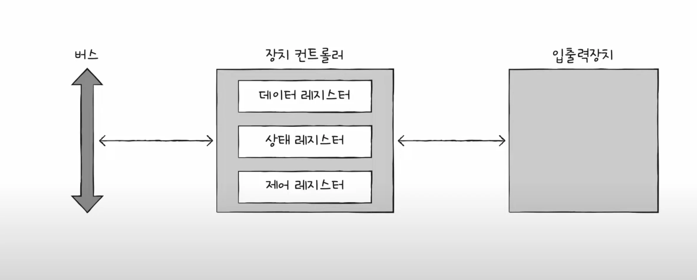
Data registers are registers that contain data to be exchanged between the CPU and input/output devices. It acts as a buffer as mentioned above. In input/output devices with a lot of data, RAM is sometimes used instead of registers.
The status register stores status information such as whether the input/output device is ready to perform an input/output operation, whether the input/output operation has been completed, and whether there are any errors in the input/output device.
Control registers store control information and commands about what the input/output device is to do.
device driver
A program that detects and controls the operation of the device controller. The operating system recognizes and runs the device driver.
Device controller is hardware, device driver is software
Memory (device driver) informs how to use the connected input/output devices through the device controller.
8.2 Various input/output methods
Let's learn about three input/output methods.
There are program input/output, interrupt-based input/output, and DMA input/output.
Programmed I/O
This is a method of controlling input/output devices using commands within a program. Interacts with the device controller as an input/output command.
Let's look at the process of backing up information stored in memory to a hard disk.
The CPU sends a write command to the control register of the hard disk controller. The hard disk controller checks the status of the hard disk and, if it is ready, marks it as ready in the status register. The CPU periodically reads the status register to check whether the hard disk is ready, and when it determines that the hard disk is ready, it writes the information about the memory to be backed up to the data register. Repeat steps 1 to 3 until the backup task is complete.
To summarize, the CPU reads and writes the register values of the device controller.
So how can the CPU communicate with the registers inside the various device controllers?
Program input/output methods include memory-mapped input/output and isolated input/output.
Memory-mapped I/O is a method that considers the address space for accessing memory and the address space for accessing input/output devices as a single address space. Commands for accessing unified memory and commands for accessing input/output devices are used.
Isolated I/O is a method of separating the address space for memory and the address space for input/output devices. Because they use different buses, they use independent commands.
Interrupt-based I/O
When the device controller sends an interrupt request signal to the CPU, the CPU temporarily backs up what it was doing and executes the interrupt service routine.
Let's learn how to handle simultaneous interrupts.
There are two ways to process: sequentially and priority-based.
Since it is realistically impossible to process sequentially, if an NMI (Non-Maskalbe Interrupt) interrupt occurs that cannot be ignored even if the interrupt bit in the flag register is enabled or the interrupt bit is disabled, the CPU processes the interrupt with the highest priority first.
The processing method that reflects priority mainly uses hardware called PIC (Programmable Interrupt Controller).
The PIC is connected to multiple device controllers, determines the priorities of hardware interrupt requests sent by the device controllers, and then informs the CPU which hardware interrupt needs to be processed now.
DMA input/output (Direct Memory Access I/O)
The two methods above have in common that the CPU drives the movement of data between the input/output device and memory, and the data being moved must also pass through the CPU.
Since the CPU processes operations for input/output devices, the CPU burden increases. The DMA method, which allows the memory of input/output devices to interact without going through the CPU, has been introduced to improve this.
As the name suggests, it is an input/output function that allows the device controller to directly access memory. It requires a piece of hardware called a DMA controller connected to the system bus.
When the CPU commands an input/output operation to the DMA controller, the DMA controller interacts with the device controller on behalf of the CPU. When the task is finished, the DMA controller interrupts the CPU to notify it that the task is finished.
Ultimately, the CPU is only involved in input/output operations.
However, since the system bus is a shared resource, the CPU and DMA controller cannot access it simultaneously. DMA's use of the system bus is called cycle stealing.
Finally, let's learn about the connection method between the DMA controller and the device controller, and the input/output bus.
When the device controller is directly connected to the system bus, the system bus is used twice during the DMA process. This means that situations where the CPU cannot use the system bus often occur.
This can be solved by connecting the DMA controller and device controllers to a separate bus called the input/output bus.
Types of input/output buses include the PCI (Peripheral Component Interconnect) bus and the PCI Express (PCIe) bus.
Nowadays, it is also equipped with a dedicated input/output processor (input/output channel).
Ch.09 Starting the Operating System
9.1 Why You Need to Know Your Operating System
operating system
All programs require system resources to run.
An operating system is a program that manages system resources and allocates resources needed by programs.
Since the operating system is also a program, it is loaded into memory, but it is loaded into the kernel area and executed.
The operating system manages where applications are loaded into memory, when they are executed, and when they are terminated.
The operating system also manages the CPU. Because the CPU can only run one program at a time, it manages which programs the CPU is allocated to.
Why You Need to Know Your Operating System
An operating system is a program for programs, not a program for developers.
When developers develop programs, the operating system handles the parts that developers don't have to worry about.
9.2 The Big Picture of the Operating System
The heart of the operating system, the kernel
The kernel is the core service of the operating system that provides the ability to access and manipulate resources and ensures that programs run correctly and safely.
Dual mode and system calls
Applications cannot access resources directly.
The operating system provides system calls that allow applications to access resources.
A system call is a call to a function in the kernel area of the operating system.
Dual mode is a method of dividing the mode in which the CPU executes instructions into user mode and kernel mode.
A program running in user mode must change to kernel mode through a system call to access operating system services that provide access to resources.
A system call causes a software interrupt to change to kernel mode.
Core services of the operating system
A running program is called a process.
Normally, the CPU can only run one process at a time, so they run alternately.
The operating system manages which processes are allocated the CPU, a topic covered in Chapter 10.
Every process requires resources to run.
The operating system allocates resources that processes need and manages their use of those resources.
Resource management includes CPU scheduling, memory management, file management, and input/output management.
This will be covered in the following content.
Ch.10 Processes and Threads
10.1 Process Overview
Check the process yourself
A foreground process is a process that runs in a space that is visible to the user.
A background process is a process that runs in a space that is not visible to the user.
There are two types of background processes: those that can interact directly with the user, and those that cannot.
A process that runs in the background without user interaction is called a daemon or service.
Process Control Block
Every process requires a CPU to execute.
The operating system manages processes using a data structure called a Process Control Block (PCB).
Switch processes via timer interrupts.
The process control block contains the process's state, program counter, registers, stack pointer, stack, process number, process priority, and resources used by the process.
Process ID (PID): A unique number used to identify a process. Register value: A value that changes while a process is running. Contains register values including the program counter. Process Status: Indicates the current status of the process. CPU scheduling information: Includes process priorities, pointers to schedule queues, etc. Memory management information: Includes address ranges of memory used by the process, pointers to page tables, etc. List of files and input/output devices used: Includes pointers to input/output devices used by the process.
Context Switching
Context: Intermediate information that must be remembered to resume process execution.
A context switch is when a process uses the CPU and then allows another process to use the CPU.
Process memory area
The process is stored in the user area divided into code area, data area, heap area, and stack area.
Code area (text area): Instructions written in machine language are stored. This is a read-only area where writing is prohibited. Data area: Global and static variables are stored here. Initialized data is stored in the data area, and uninitialized data is stored in the BSS area. Heap area: This is an area that can be directly allocated by the programmer. Be careful, as this may cause memory leaks. Stack area: Local variables and parameters related to function calls are stored here. When a function call is finished, it is removed from the stack area.
10.2 Process States and Hierarchy
Process status
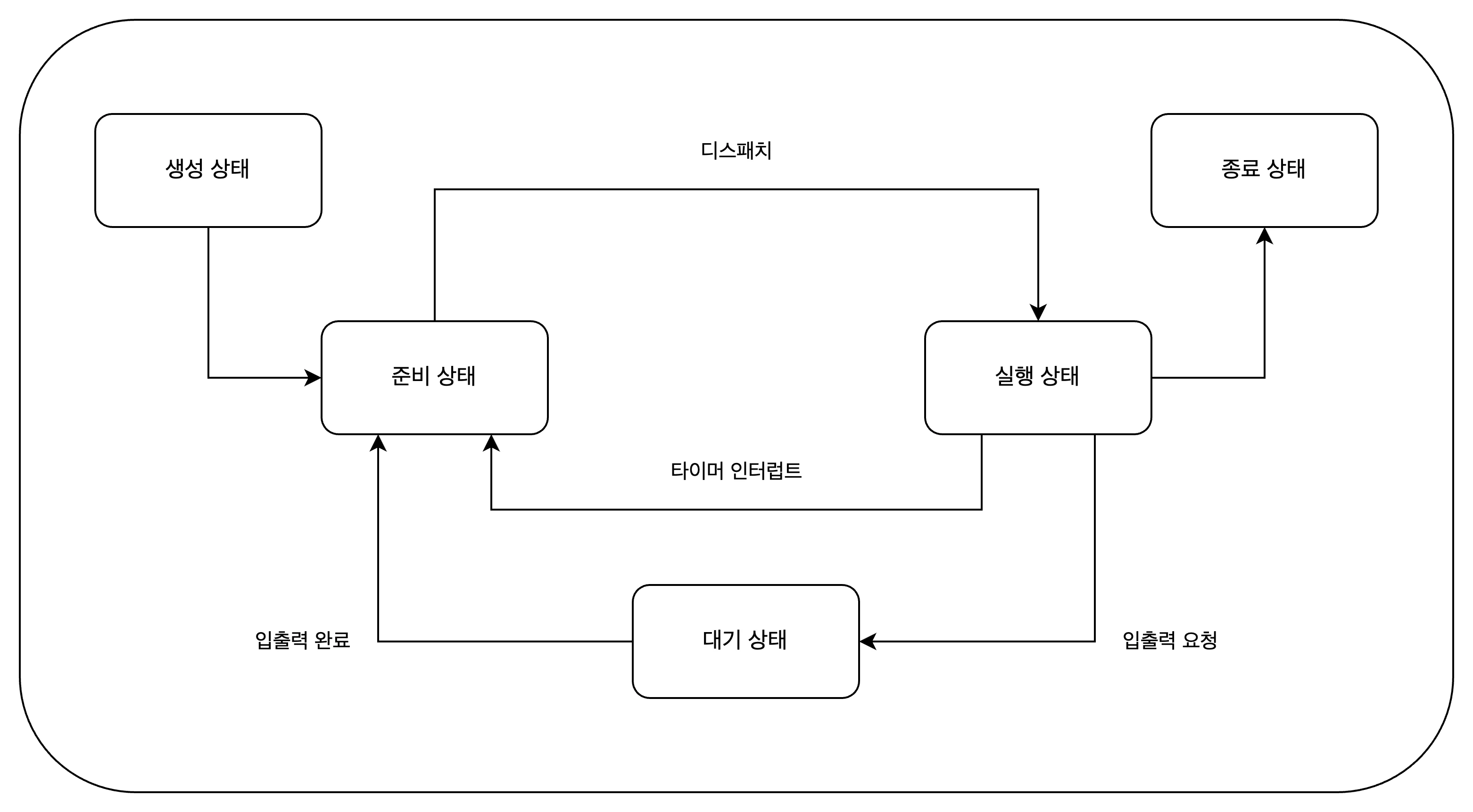
Process status indicates what the process is currently doing.
Creating state: The process is being created. It is loaded into memory and assigned a PCB. Ready state: The process is loaded into memory and waiting for the CPU. The process of transitioning from a ready state to a running state is called dispatch. Running state: The process is occupying the CPU and executing instructions. Waiting state: The process is waiting for input/output. When input/output is complete, it switches to the ready state. Terminate state: The process has finished executing and terminated. The operating system frees the PCB and memory.
Process Hierarchy
Processes are managed in a hierarchical structure. A parent process can create child processes, and child processes can share the resources of the parent process.
Since the parent process and the child process are separate processes, they each have their own PCB.
Process creation techniques
A parent process can create child processes through fork and exec.
A parent process creates a copy of itself as a child process through the fork system call.
A child process overwrites its memory space with another program via the exec system call.
Verification problem
- Below is a process state diagram showing the process states.
10.3 Thread
The threads covered here are software threads.
Processes and Threads
A thread is a unit of execution flow that constitutes a process. A process can have one or more threads.
Many programs perform parallel processing by creating multiple threads in a single process. These programs are called multithreaded programs.
A thread consists of a thread ID, a program counter, a set of registers, and a stack. It has the bare minimum information required to run.
Threads share the resources of a process.
Multiprocessing and multithreading
Running multiple processes simultaneously is called multiprocessing, and running processes simultaneously with multiple threads is called multithreading.
Processes cannot share resources, but threads can share the resources of a process.
Ch.11 CPU Scheduling
CPU scheduling is how the operating system allocates CPU resources to processes.
11.1 CPU Scheduling Overview
Process Priority
Processes have priorities. Higher priority processes are allocated the CPU first.
Usually, the priority of an interactive process that performs a lot of input/output work is higher than that of a CPU-bound process.
The priority of a process is stored in the process control block (PCB).
Scheduling Queue
Although priorities are stored in the PCB, it is inefficient for the operating system to search through all processes to find the next process to use the CPU.
To solve this, the operating system uses a scheduling queue. It is not necessarily FIFO.
The ready queue is used when a process is ready to use the CPU, the wait queue is used when a process is waiting for input/output, and the done queue is used when a process has terminated.
Waiting queue: Processes requesting the same device are stored in the same queue.
Preemptive and non-preemptive scheduling
Preemptive scheduling is when the operating system forcibly stops a process that is using the CPU and runs another process.
Non-preemptive scheduling means that the operating system does not forcibly terminate a process when the process is using the CPU.
Each has its own pros and cons.
11.2 CPU Scheduling Algorithm
First-Come First-Served Scheduling (FCFS)
Non-preemptive scheduling is a scheduling method that assigns the CPU to processes in the ready queue in the order in which they arrive.
A convoy effect may occur.
Shortest-Job-First Scheduling (SJF)
Non-preemptive scheduling is a scheduling method that gives priority to the process with the shortest CPU usage. It can also be implemented in a preemptive manner.
Round-Robin Scheduling (RR)
It is a preemptive scheduling that uses first-come, first-served scheduling + time slice.
A time slice is the amount of time a process can use the CPU.
When the time slice ends, the process moves to the back of the ready queue.
Shortest-Remaining-Time Scheduling (SRT)
It is a preemptive scheduling that uses round robin scheduling + shortest job first scheduling.
Priority Scheduling
It is a non-preemptive scheduling method that assigns a priority to each process and allocates the CPU to processes with higher priorities.
Starvation may occur. Aging is a method to solve this problem.
This is a way to increase the priority of a process that has not used the CPU for a long time.
Multi-Level Queue Scheduling
It is an advanced form of priority scheduling.
Create multiple ready queues by priority, and give priority to CPU allocation to processes in queues with higher priorities.
Multi-Level Feedback Queue Scheduling
It is an advanced form of multi-level queue scheduling.
If there is a newly ready process, it is placed in the highest priority queue and executed during the time slice.
If the execution does not finish during the time slice, the priority is lowered and put in the next priority queue.
Processes that require long CPU usage are gradually given lower priority.
Starvation can be prevented by using aging techniques to raise the priority of lower priority processes.
Verification problem
- Assuming that processes A, B, C, and D are inserted into the ready queue in that order, in what order will the processes be allocated the CPU if the FIFO scheduling algorithm is applied?
ABCD
Ch.12 Process Synchronization
12.1 What is Synchronization?
Concurrently running processes cooperate with each other to perform tasks.
Consistency of resources must be ensured throughout this process.
Meaning of synchronization
Synchronization means that processes cooperate with each other to perform tasks.
Synchronization includes synchronization for execution order control and synchronization for mutual exclusion.
- Synchronization for Execution Order Control: The Reader-Writer Problem
Writer: Process that saves values to a file Reader: Process that reads values from a file
The two have an order of execution. The Reader process must wait until the Writer process writes the value to the file.
- Synchronization for Mutual Exclusion: Bank Account Problem, Producer Consumer Problem
It prevents simultaneous use of non-shareable resources.
Shared resources and critical zones
Shared resources: Resources shared by multiple processes or threads.
There are global variables, files, input/output devices, memory, etc.
Critical section: Code that accesses resources that would otherwise cause problems if executed concurrently.
No other process can enter the critical section until the process that entered it exits the critical section.
Simultaneous access to critical sections can break resource consistency, which is called a race condition.
Three Principles for Synchronization for Mutual Exclusion
- Mutual exclusion: Once a process enters its critical section, no other process can enter it.
- Progress: If no process has entered the critical section, a process wishing to enter the critical section must be able to do so.
- Bounded Waiting: If a process wants to enter its critical section, it must be able to enter its critical section at some point.
12.2 Synchronization Techniques
Learn about mutex locks, semaphores, and monitors.
mutex lock
It is a synchronization technique for mutual exclusion.
A mutex lock consists of one global variable and two functions.
- lock: a global variable shared by processes
- acquire: The role of locking the critical section
- release: The role of unlocking the critical section
Mutex locks are locked by calling the acquire function before entering the critical section, and unlocked by calling the release function when exiting the critical section.
semaphore
A semaphore is a synchronization tool similar to a mutex lock, but in a more general way.
It can be used even when there are multiple shared resources.
A semaphore consists of one global variable and two functions.
- semaphore: A global variable that indicates the number of processes that can enter the critical section.
- wait: A role that indicates whether it is okay to enter the critical section or whether we need to wait.
- signal: The role of sending a signal that it is okay to enter the critical area.
The wait function puts the process into a waiting state if no resources are available and puts the PCB of the process into the waiting queue for the semaphore.
Semaphores can also be used to synchronize execution order.
Set the semaphore variable S to 0, call the signal function after the process to be executed first, and call the wait function after the process to be executed later.
monitor
It is a synchronization technique used by Java.
A monitor manages shared resources and interfaces for accessing those resources. To access shared resources, you must access them through an interface.
Synchronization for mutual exclusion uses a queue for the interface.
Synchronization for controlling execution order uses condition variables. Use a queue for condition variables.
Verification problem
- What is incorrect about mutex locks and semaphores?
- If you use a semaphore, you will definitely have to wait a long time.
Ch.13 Deadlock
13.1 What is a deadlock?
The Dining Philosophers Problem
This happens when two parties are waiting for each other to occupy a resource.
Resource Allocation Graph
This is a graph showing the situation when a deadlock occurs.
Processes are represented by circles, and resources are represented by squares.
The number of resources is represented by dots within the resource square.
If a process is using a resource that has been allocated to it, an arrow is drawn from the resource to the process.
If a process is waiting for some resource, draw an arrow from the process to the resource.
The resource allocation graph in which a deadlock occurs takes the shape of a circle.
Deadlock occurrence conditions
For a deadlock to occur, all four of the following conditions must be met:
- Mutual exclusion: A resource can only be used by one process at a time.
- Hold and wait: A process waits for another resource while holding the allocated resource.
- No preemption: If a process is holding a resource, another process cannot forcibly take it away.
- Circular wait: Each process has resources that the next process requires in a circular manner.
13.2 How to resolve deadlocks
There are three main ways to resolve deadlock.
Preventing deadlocks
- Remove mutual exclusion conditions. It's about making all resources shareable. It's not realistic.
- Remove the occupied waiting condition. After a resource is allocated, it is not requested for other resources. Reduces resource utilization.
- Remove non-preemptive conditions. Allows a process holding a resource to take the resource away when it requests another resource. It is effective only for resources that can be preempted, but not for resources that cannot be preempted.
- Remove the circular waiting condition. Eliminate cycles by determining the order in which resources are requested. Reduces resource utilization.
Deadlock avoidance
We assume that the deadlock is caused by indiscriminate resource allocation. Therefore, resources are allocated only when it is expected that deadlock will not occur before allocating resources.
Safe sequence: A sequence that does not cause deadlock even if the system's resources are allocated Safe state: A state in which a safe sequence exists. Unsafe condition: A condition in which there is no safe sequence.
Recovery after deadlock detection
It is a method of taking action after the fact.
Recovery through preemption: A method of giving resources to one process at a time until the deadlock is resolved. Recovery by forcibly terminating a process: A method of forcibly terminating a deadlocked process until the deadlock is resolved.
Ch.14 Virtual Memory
14.1 Contiguous Memory Allocation
Contiguous memory allocation is a method of allocating contiguous memory space within a process.
Swapping
This refers to moving currently unused processes to the swap area of auxiliary memory and loading the processes to be executed into the newly created empty space.
Swapping allows processes to run concurrently even if the amount of memory space they require is larger than the actual memory size.
Memory allocation
For a process to run, it must be loaded into an empty space in memory. There are three loading methods: first fit, best fit, and worst fit.
First-fit is a method in which the operating system loads a process into the first free space it finds when searching for free space in memory. It can minimize searches and has fast allocation. Best-fit is a method in which the operating system searches all free spaces in memory and then allocates to the smallest space that can be loaded. Worst-fit is a method in which the operating system searches all free spaces in memory and then allocates to the largest space that can be loaded.
External fragmentation
Contiguous memory allocation, which places processes contiguously in memory, is not an efficient way to use memory. This is because a situation called external fragmentation occurs where there are multiple small empty spaces within the memory.
External fragmentation makes it difficult to load processes larger than the free space, reducing memory efficiency.
External fragmentation can be resolved through memory compression. Memory compression is a method of arranging processes in order from their starting addresses in memory.
Verification problem
- Find the correct explanation of how memory is allocated in the following examples. > First fit: A method of placing a process in the first available space found > Worst fit: A method of placing a process in the largest space where a process can be loaded > Best fit: A method of placing a process in the smallest space where a process can be loaded
14.2 Virtual Memory Management through Paging
Paging is one of the virtual memory management techniques.
What is paging?
This is a method of dividing a process into pieces of a certain size and loading them into memory discontinuously. This method divides the logical address space of a process into fixed units called pages, divides the physical address space of memory into fixed units called frames , and then maps pages to frames.
Swaps in paging are called page in and page out.
Page table
This is a table that indicates which frame the pages that make up the process are loaded into. This is a table that maps page numbers to frame numbers.
Internal fragmentation can occur due to processes requiring memory space smaller than the size of one page. Each process has a page table, and each page table is stored in the Process Table Base Register (PTBR) within the CPU.
Placing the page table in memory doubles the memory access time. For this purpose, TLB (Translation Lookaside Buffer) is used.
The TLB is a cache of page tables, storing some of the contents of the page tables. TLB stores pages that have been recently used.
If the logical address that the CPU is trying to access is in the TLB, it is called a TLB hit; if not, it is called a TLB miss.
Address translation in paging
To access a specific address, you need to know which page or frame you want to access and how far away the address you want to access is from that page or frame.
A logical address in a paging system consists of a page number and an offset. This is converted into a physical address (frame number, displacement) through the page table.
Page table entry
A page table entry represents each row in the page table. It also includes information other than page numbers and frame numbers.
Valid Bit: Indicates whether the page is currently accessible. If the valid bit is 0, the page is not loaded into memory. This is called a page fault.
Protection bit: A bit for page protection. If the protection bit is 0, it is read-only, and if it is 1, it is read/write.
Reference bit: Indicates whether the CPU has accessed the page. If the reference bit is 0, the page was not accessed.
Modification bit: Indicates whether the CPU has had a write access to the page. If the modification bit is 0, no write access was made to that page.
Additional lectures
Advantages of Paging - Copy on Write
Processes do not share resources by default. Theoretically, fork() copies the memory of the parent process as is, which causes problems such as process creation time delay and memory waste .
Copy-on-write means that the child process points to the same frame as the parent process, and then copies the page to a separate space when a write operation is performed.
Hierarchical paging
This is a method of paging page tables to place pages in multiple levels.
It uses a logical address consisting of three parts: outer page number, inner page number, and displacement.
When a page fault occurs, the number of memory references increases, which can lead to performance degradation.
14.3 Page Replacement and Frame Allocation
Demand paging
Demand paging is a technique that loads only the pages that are requested. Page replacement and frame allocation are required.
Page replacement algorithm
A good page replacement algorithm is generally one that produces few page faults.
The FIFO page replacement algorithm (First In First Out) is an algorithm that replaces the page that was loaded the longest time ago.
The second-chance page replacement algorithm was created to compensate for the shortcomings of the FIFO algorithm. The second-chance algorithm replaces pages with a reference bit of 0 by adding a reference bit.
The optimal page replacement algorithm is one that takes into account the number of times it is referenced by the CPU. Pages that need to remain in memory for a long time will have a high number of references, and pages are replaced accordingly.
The LRU (Least Recently Used) page replacement algorithm is an algorithm that replaces the page that has not been referenced for the longest time.
Thrashing and Frame Allocation
A situation where page faults occur frequently may not only be due to a bad page replacement algorithm, but also because the process itself has fewer frames available.
Thrashing is a problem in which a process spends more time paging than it actually runs, resulting in poor performance.
Thrashing can be solved by determining the minimum number of frames each process needs and allocating appropriate frames to the processes.
Let's learn about frame allocation methods. The static allocation method is as follows:
Equal allocation is a method of allocating the same number of frames to each process. It feels irrational.
Proportional allocation is a method of allocating the number of frames to each process in proportion to the process size.
The dynamic allocation method is as follows:
The working set model is a method in which the CPU assigns only the number of pages that have been primarily referenced during a specific period of time to a frame.
The working set can be obtained through the pages referenced by the process and the time interval.
The page fault frequency model is a method of allocating frames based on the number of times page faults occur.
We start with the assumption that if the page fault rate is too high, the process has too few frames, and if the page fault rate is too low, the process has too many frames.
Set upper and lower limits and allocate frames within that range.
Optional mission
If a process has 3 frames available and the page reference string is '2414523423', how many page faults will occur if this page is referenced using FIFO, optimal page, and LRU page replacement algorithms?
FIFO: 2414_5234_23 -> 4 times Optimal: 2414_5_2_3_423 -> 2 times LRU: 2414_5234_23 -> 4 times
Ch.15 File System
15.1 Files and Directories
A file system is a program within an operating system that manages files and directories.
file
It refers to a collection of related information stored in auxiliary storage devices such as hard disks or SSDs.
The information that makes up a file includes information for executing the file and additional information. You can tell what type of file it is by its extension.
Directory
These days, most forts use a tree-structured directory structure. A tree-structured directory manages files and directories hierarchically.
The top-level directory is called the root directory. Naturally, you can use directories to express the location of a file/directory, i.e., the path.
Absolute path: Path starting from the root directory Relative path: Path starting from the current directory
A directory entry stores the names and locations of files/directories contained in the directory.
15.2 File System
Partitioning and Formatting
Partitioning refers to the task of dividing a storage device into logical areas.
Formatting is the process of setting up a file system, deciding how to manage files, and preparing to write new data.
File allocation method
The operating system reads and writes files/directories in block units.
There are two main ways to allocate auxiliary memory. There are continuous and discontinuous allocations.
Contiguous allocation: A method of storing files in contiguous blocks. Directory entries contain the file name, the address of the first block, and the block length.
It has the disadvantage of causing external fragmentation.
There are two types of discontinuous assignment: linked assignment and indexed assignment.
Linked allocation: A method of storing files in discontinuous blocks. Store the address of the next block in part of each block.
It has the disadvantage that it must be read sequentially, starting from the first block, and blocks after that block cannot be accessed in case of hardware failure or error.
Indexed allocation: A method of managing all block addresses of a file in a single block called an index block. Easy to access any location within the file.
Directory entries store the file name and the index block address.
Exploring the File System
FAT file system: A file system that uses the concatenated allocation technique of the discontinuous allocation technique. The block addresses of files are stored in a special block called the File Allocation Table (FAT).
Directory entries in the FAT file system contain the file name, extension, attributes, reserved area, creation time, last access time, last modification time, first block address, file size, etc.
Unix file system: A file system that uses index allocation techniques. The block address of the file is stored in a special block called the index block (i-node).
Directory entries in a Unix file system contain an i-node number and a file name.
It can store file attribute information and 15 block addresses. Twelve of the block addresses store direct block addresses, the 13th stores single indirect block addresses, and the 14th stores double indirect block addresses.
The 15th one stores the triple indirect block address.